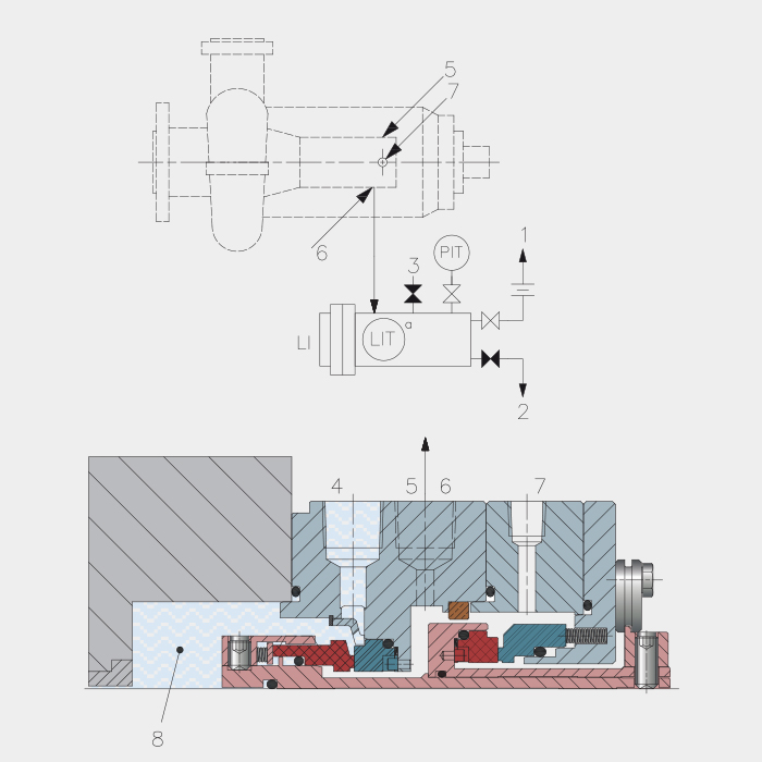
PLAN 75
ELEMENTS
1. To the gas recovery system
2. To the liquid recovery system
3. Test connection (if specified)
4. Flushing (F)
5. Containment seal vent (CSV)
6. Containment seal drainage (CSD)
7. Buffer gas inlet (GBI), plugged if not made with PLAN 72
8. Stuffing box
LI. Level indicator
LIT. Level transmitter with display
PIT. Pressure transmitter with display
(a) If specified
- Description
- CONSTRUCTION FEATURES
- MAIN FUNCTIONS
- Additional information
Description
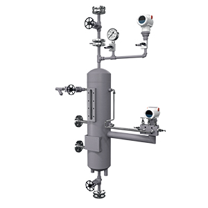
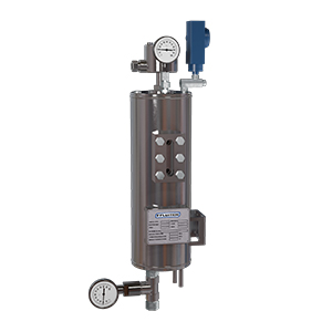
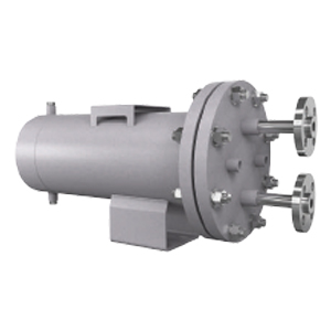
Collection and leakage control system, for process fluids having mixed phase in contact with the atmosphere, used when reducing emissions level to the atmosphere is a must. Used in combination with a dual seal (2CW-CS), where the outer back-up dry contacting seal is equipped with Fluigrid technology. Gaseous leakage is taken to the gas recovery system (usually represented by the flare), while liquid leakage is collected into the tank. Flushing plan that can be used in combination with Plan 72.
- Tank material: AISI 316.
- Level indicator availability, for local control by operators.
- The pressure transmitter detects any abnormal gas flow rate, indicating any critical points in the seal operations.
- Level transmitter indicates the presence of excessive liquid in the tank.
- Reduction of process fluid leakage to the atmosphere.
- Alternative to dual mechanical seal and reservoir (i.e. Plan 52).
CAUTION!
The tank must be placed at a lower level than mechanical seal drain connection.
Additional information
| Category | Auxiliary Systems, Rilevamento Perdite |
|---|---|
| Market | |
| Application | |
| Configuration Seal |